Eyetracktive Design
Cut it. Glue it. Use it.
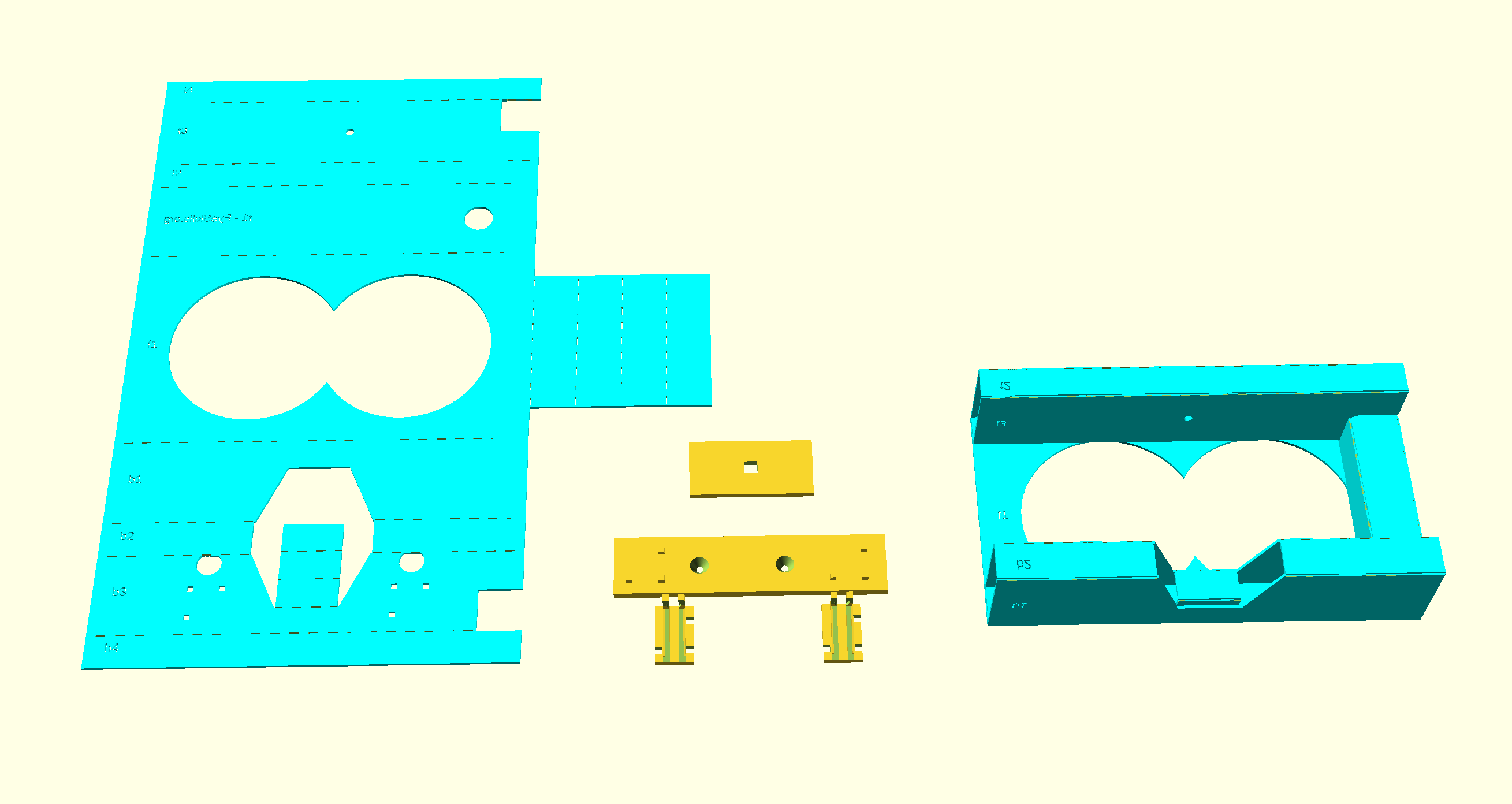
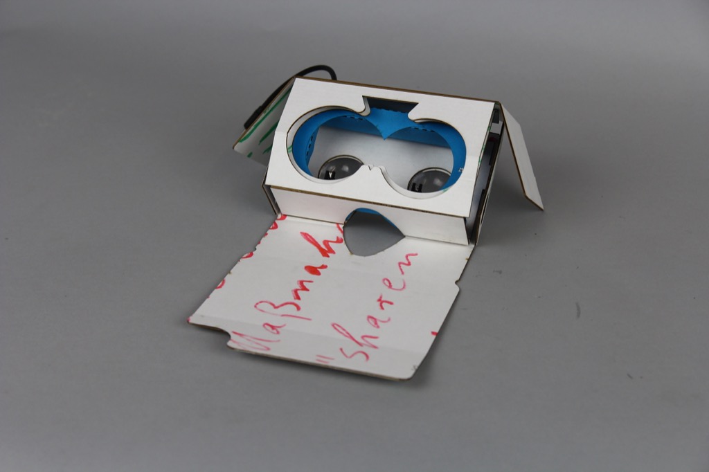
The Camera Insert
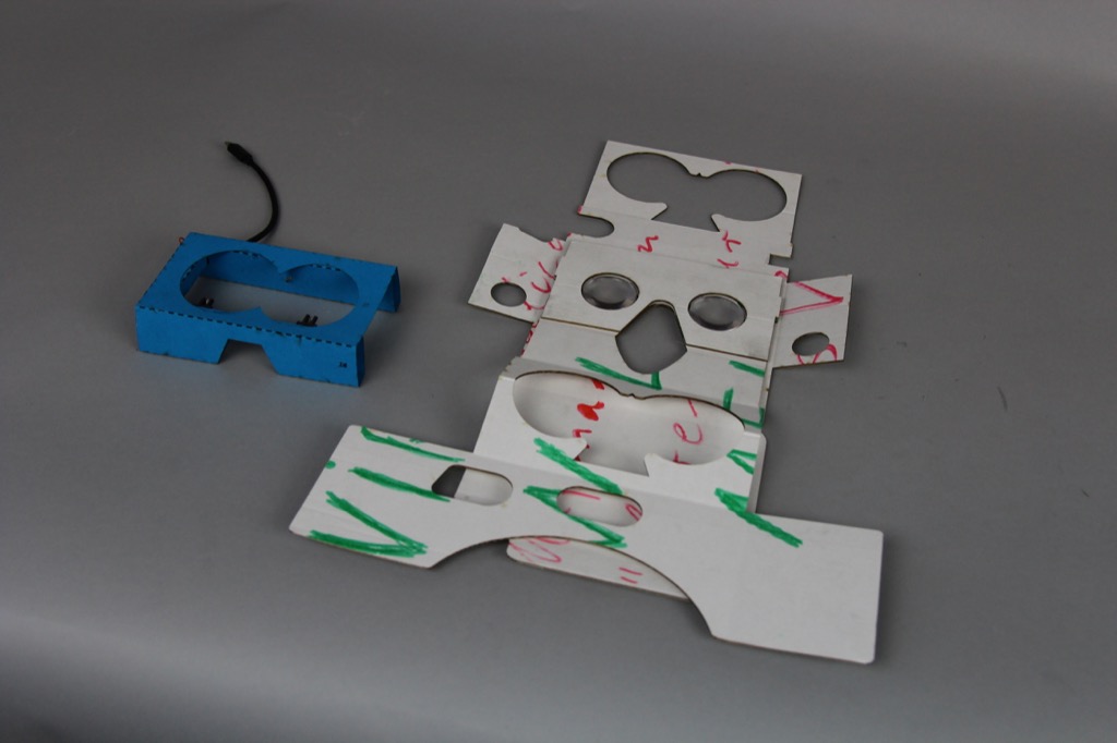
At the heart of EyeTractive is a piece of card. This replaces the third section of a regular google cardboard second generation.
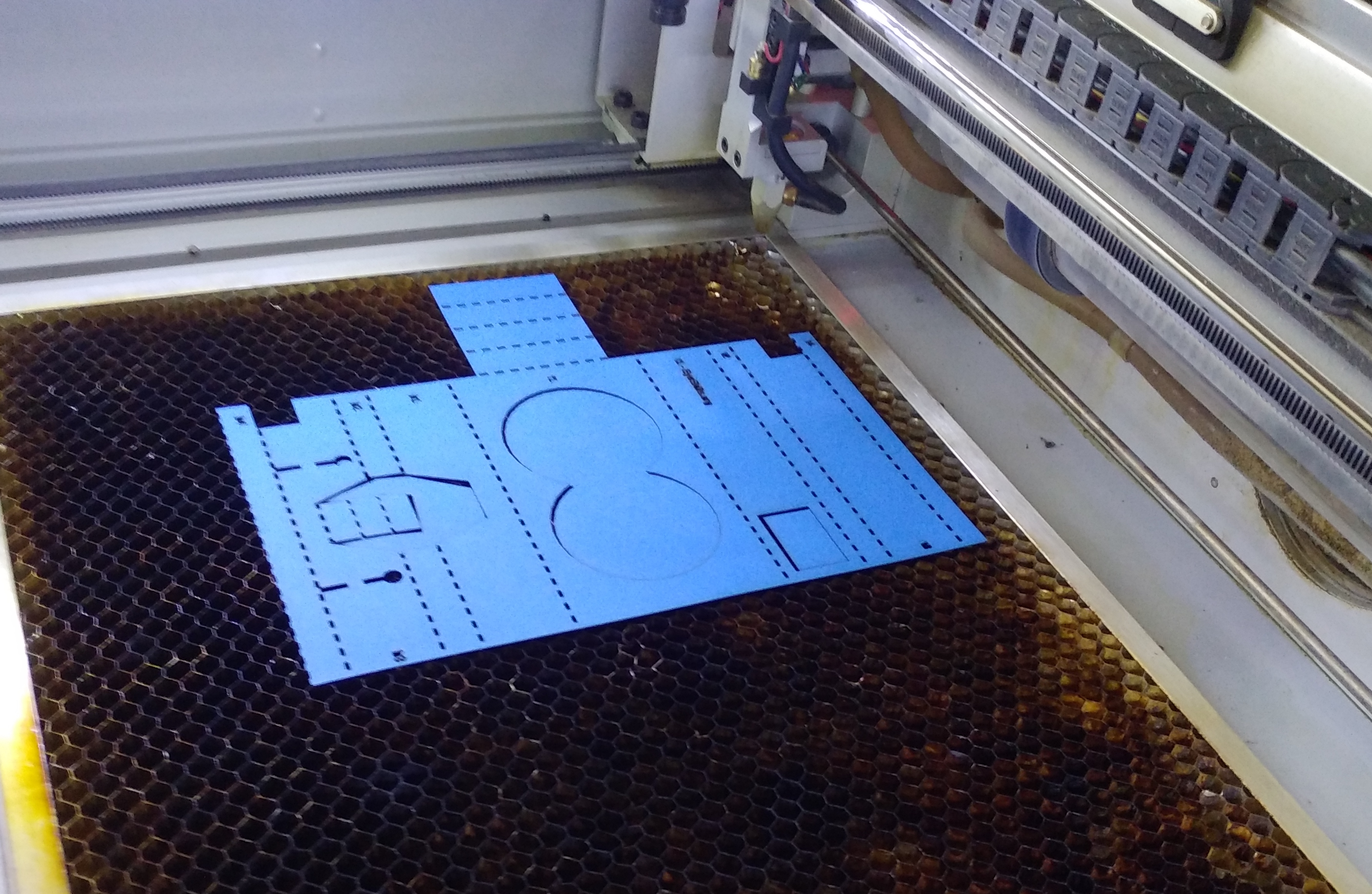
You will be replacing it with this file. You can print this out and cut along the lines with a knife, or feed it into a laser cutter. We recommend using 2mm stiff card.
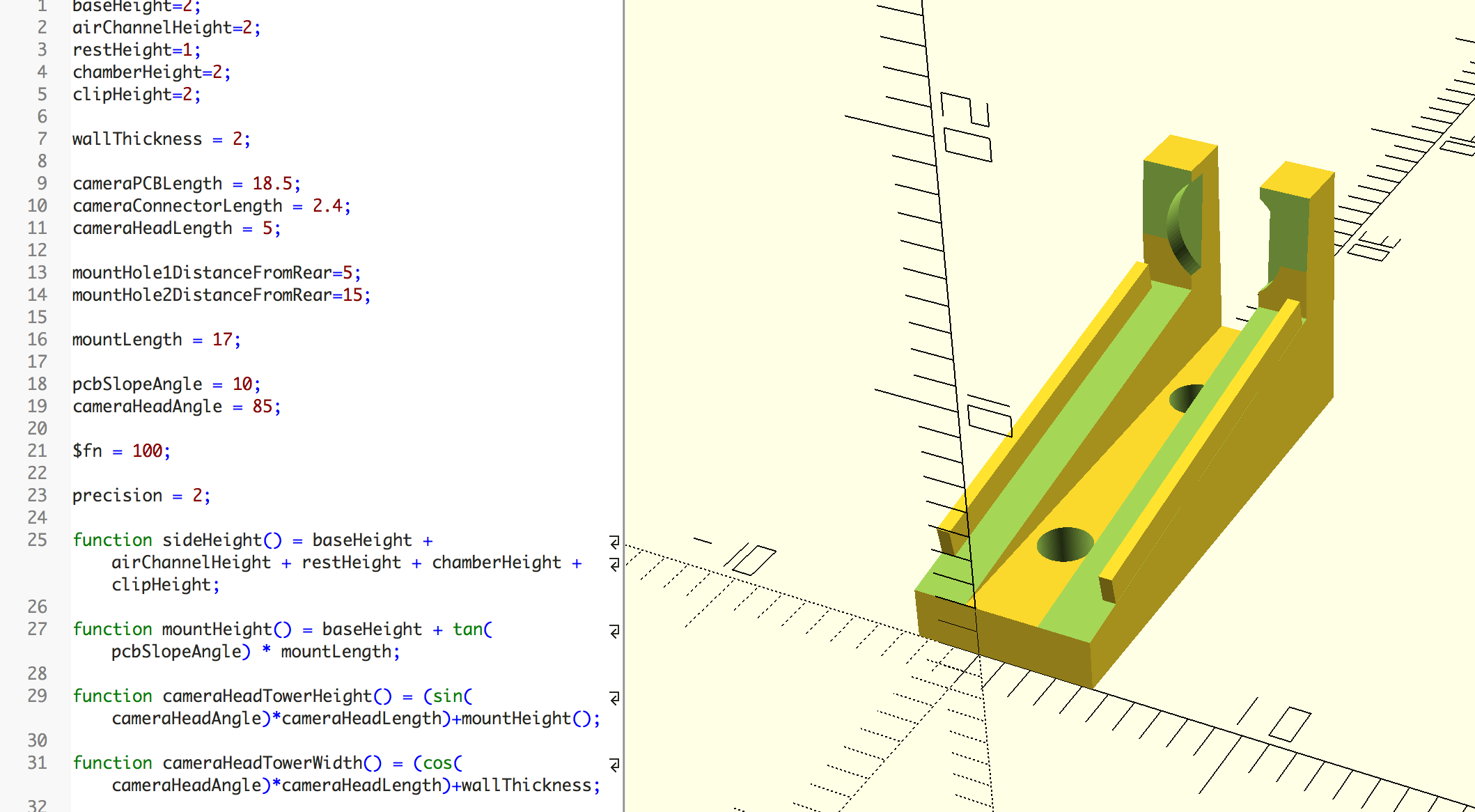
Would you like to evolve the design? Here are the original working files. Just download the open source and free software OpenSCAD to edit them.
We will talk about how to assemble it later in this guide, once we have gone through all the parts that will fit inside it!
Assembling the Core
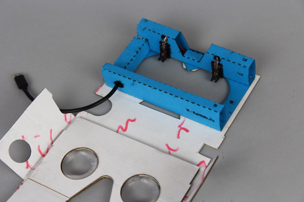
These are the main parts you will need to assemble the core. There is the insert to hold the electronics and cameras (blue card), the electronics themselves (consisting of a small hub, the guts of two endoscopic cameras, and cabling), 3D printed mounts for holding the cameras in a position where they can see the eyes, and an installation aide.
You can read more detail on how to assemble the electonics here.

If you wish to 3D print the camera mounts, you can download the OpenSCAD files here. Printing with PLA filament is fine.
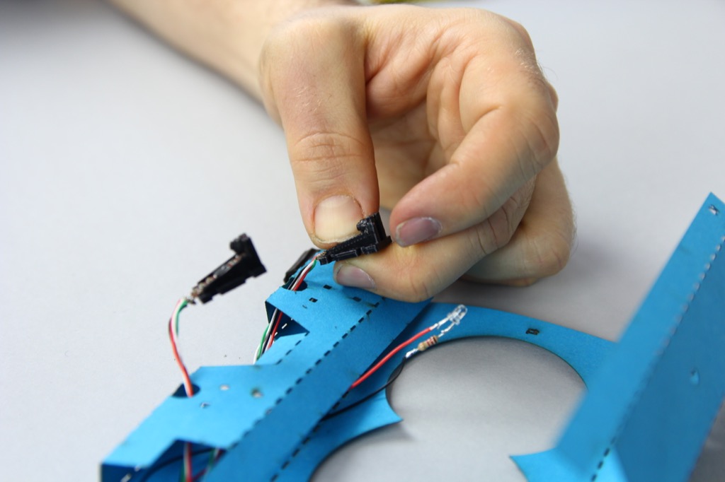
Part 1 - Putting the electronic guts in place.
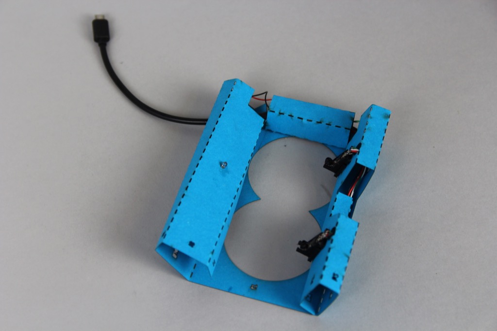
After you have assembled the electronics you will need to feed them into the cardboard core.
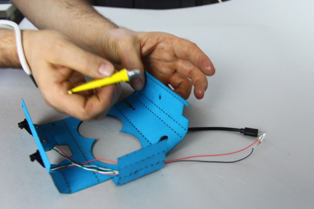
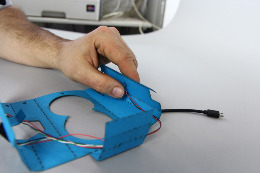
First, feed the camera PCB and lens units through the feed holes at the front of the core (b3).
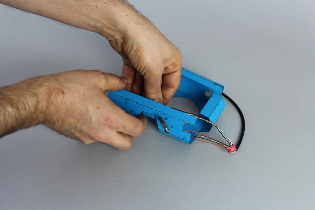
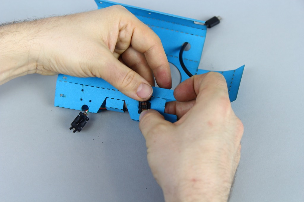
Next, feed the USB plug through the output hole at the top of the core (t1).

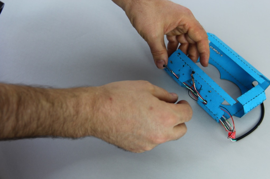
Now glue along the edges of the camera holders (leaving space for the heat to dissipate along the central channel)...

... and mount the camera lens and pcb unit into the appropriate slots on the camera holder.

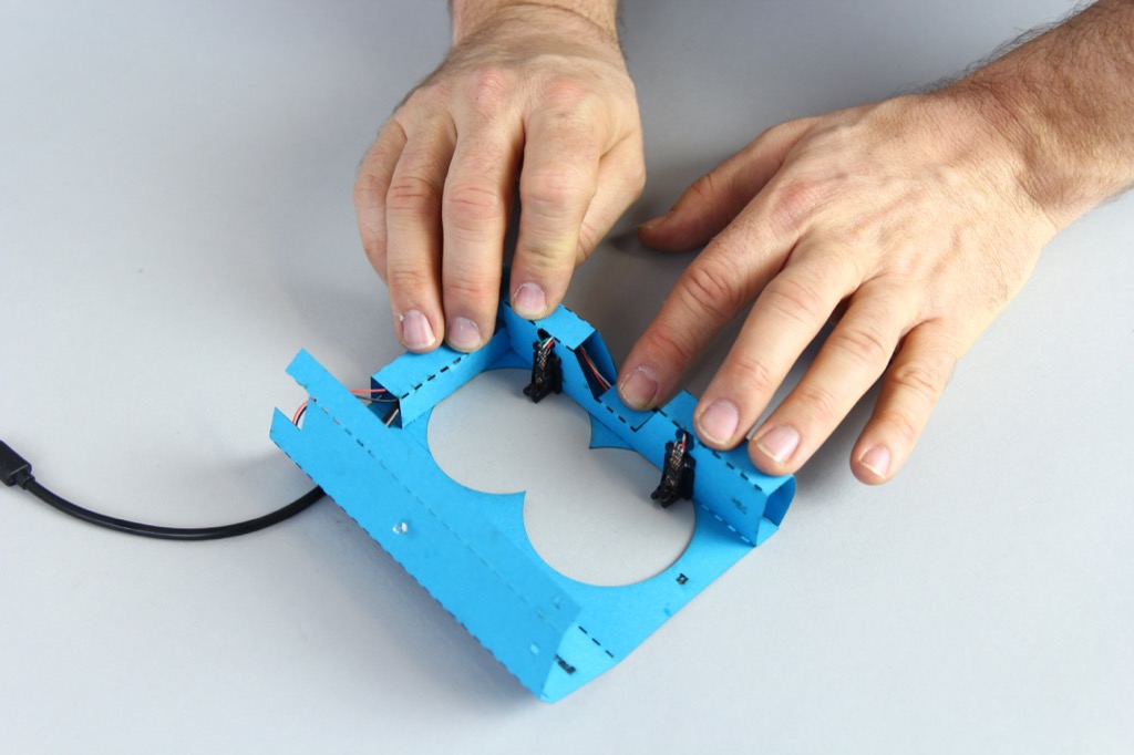
Once you have both cameras in position, you can mount the camera mounts on the core itself. Use the installation assistant to ensure that the module are mounted facing in the right direction and also in just the right position.

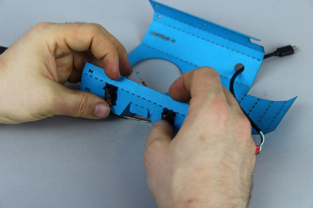
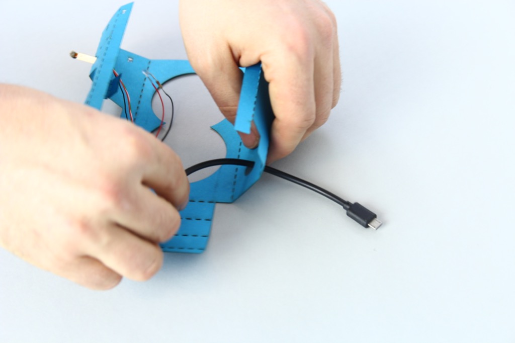
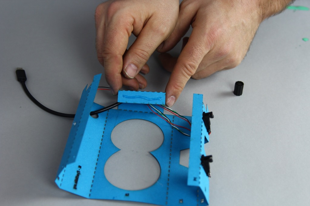
Next we're going to glue the nano-hub into position in the cabel channel that runs between the bottom and top of the core.

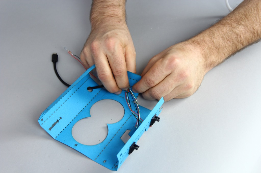
After that, we will afix the Infra Red LED at the top of the core which illuminates the eyes.

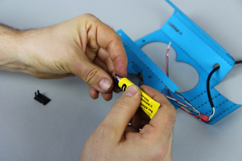
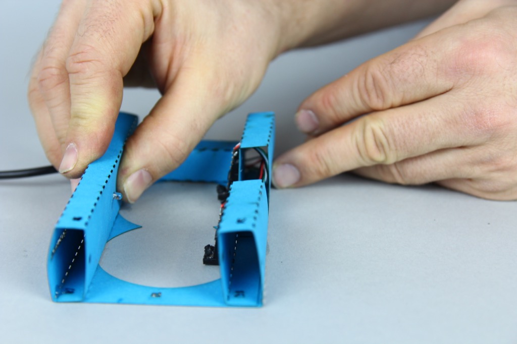
Part 2 - Folding and glueing the core.
First, glue and fold the cable channel which holds the usb hub.
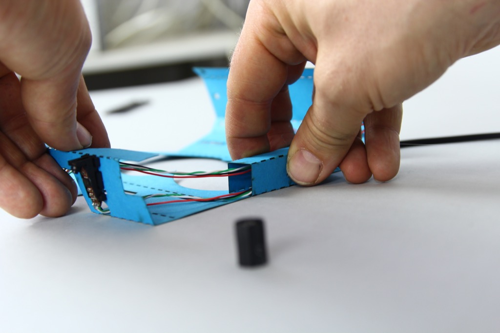
Next, glue and fold the "nose guard" around the cable coming from the left most camera.
After this, you can glue and fold the rest of the base unit...

Now you just need to glue and fold the upper-most section.
Now you are ready to place it inside the unfolded Google Cardboard V2, and fold it in.
As you may have noticed, there are several areas which could be improved. The core needs sides to glue the surrounding cardboard against, and the IR LED positioning will probably need to be rethought. It may also be desirable to add additional tabs to improve the structural firmness between the top, bottom and cable channel. Feel free to adapt the OpenSCAD design and send us an updated copy! :-)
Get in touch
Over here!